Note:
Since publishing this post, ChirpStack released their version 4 LoRaWAN network server, which significantly changes the architecture and configuration. This post goes through setting up a network with ChirpStack v3, for an updated version of this post using ChirpStack v4, see Getting Started With a Private LoRaWAN Network Using ChirpStack v4.
I have recently started experimenting with LoRa radios, and the LoRaWAN network protocol. Interestingly it seems that the LoRa ecosystem is simultaneously surprisingly open (both in specifications and implementations), while also having very little definitive documentation on how to actually get started as an indvidual hacker. As such I found the process of learning enough of the protocol to set up my own network surprisingly difficult.
This post will walk through the process of setting up my own private LoRaWAN network, from low cost hardware all the way up to the application level. While I would never claim to be an expert in LoRa or LoRaWAN, I hope someone finds this a useful reference.
LoRa and LoRaWAN Basics
LoRa (not to be confused with LoRaWAN) is a proprietary modulation and physical layer standard for low power wireless communication, originally developed in 2010 by Cycleo, which was later acquired by Semtech in 2012. The LoRa physical layer uses a “Chirp Spread Spectrum” (CSS) modulation technique to spread the signal over either 125, 250, or 500MHz bands. The use of CSS modulation, instead of the more common “Direct Sequence Spread Spectrum” (DSSS) allows LoRa to transmit over longer ranges and be more robust to many common types of interference.
The advertised range for LoRa transceivers tend to be in the 1km to 10km range, though from my research it realistically is more often on the lower end of that range. I have not tested what range I can get from my system yet, so I don’t have my own empirical data. More information about LoRa modulation and the physical layer can be found in this Application Note from Semtech, and this excellent series of blog posts.
LoRaWAN, on the other hand, is a “Low Power Wide Area Network” (LPWAN) specification, built on top of the LoRa physical layer. LoRaWAN defines a network architecture, MAC layer, and link layer protocols, primarily targeted at building low power and bandwidth sensor networks. The LoRaWAN standard is defined by the LoRa Alliance, and is published as an open standard in two primary parts: The LoRaWAN L2 Specification which defines everything except specific physical layer parameters, and the LoRaWAN Regional Parameters which defines physical layer parameters, such as frequency bands, bandwidth, etc. for specific regions of the world, in order to be compliant with local regulations.
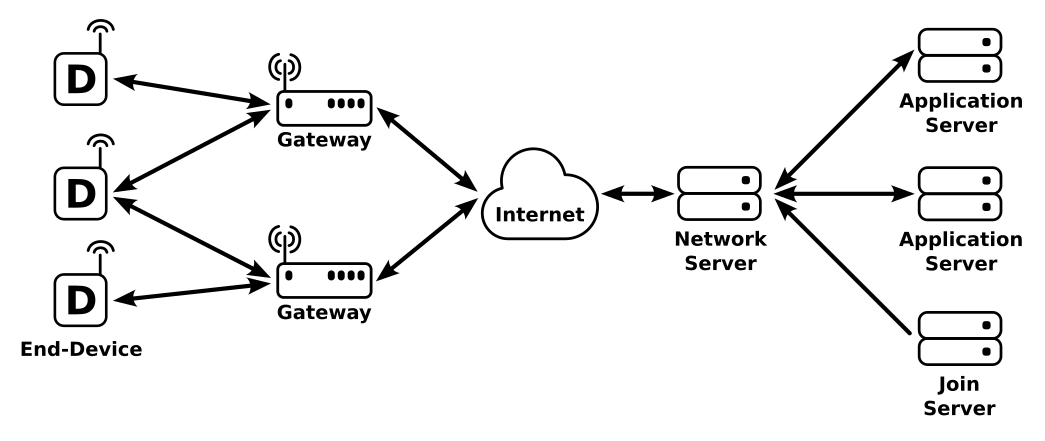
The basic architecture of a LoRaWAN network is shown above. Each LoRaWAN “End-Device” communicates with one or more “Gateway” devices over the LoRa physical layer. These gateways forward messages between the end-devices and a “Network Server” over standard TCP/IP networking. The network server manages all devices connected to one or more gateways, including device activation (joining a network), congestion control, etc. Device authentication is handled by a separate “Join Server” that interfaces with one or more network servers, and finally any non-management messages from a device are sent from the network server to an application server.
Getting Started
The simplest way to start using LoRaWAN, is to buy some LoRaWAN devices, connect them to a public network such as The Things Network, and you are good to go. While this is simple because all the network and server management is handled by someone else, I wanted to set up my own network. This was partially just to understand how all the pieces of the LoRaWAN network work, but also because I don’t have coverage from any of these networks where I live anyway.
To set up your own network you need essentially four things:
- End device hardware, generally a LoRa transceiver and a microcontroller.
- Firmware network stack to run on the end device.
- Gateway radio for the end devices to connect to.
- Gateway client and network/join server software.
End-Devices
Hardware
For end-device hardware, there are many different options, from off the shelf LoRaWAN connected sensors and devices, to bare LoRa transceiver chips. For my first foray into LoRaWAN I chose to use an integrated LoRa radio/microcontroller module, since I believe it provides the most direct development path to building my own custom device PCBs in the future, while also allowing complete programmability of the device. There are several manufactures that produce these modules with different specifications, but I chose the CMWX1ZZABZ module from muRata as it was a fairly common, low cost option.
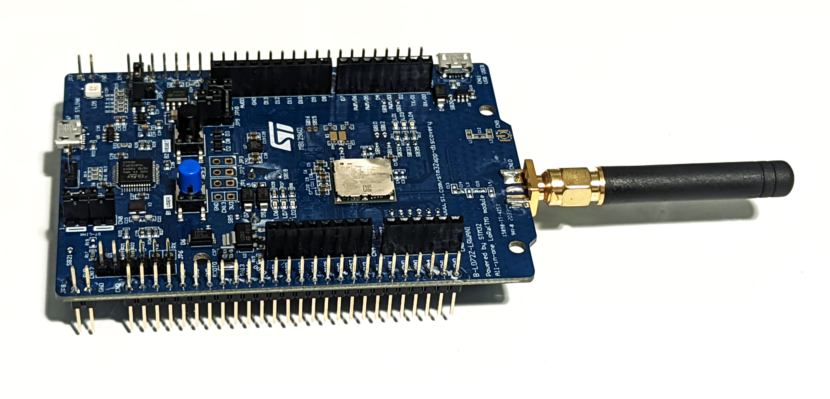
The CMWX1ZZABZ module integrates a Semtech SX1276 LoRa transceiver, RF switch, and STM32L microcontroller into single surface mount RF module that is easily integrated onto a custom PCB. The integration of a STM32 MCU is convenient, as this is a microcontroller platform that I am already familiar with. Additionally, ST Microelectronics even sells the B-L072Z-LRWAN1 development board that included everything I needed to get started building a LoRaWAN end-device.
Firmware Networking Stack
In addition to the end-device hardware, I also needed firmware that implemented the end-device side of the LoRaWAN protocol. Fortunately, Semtech have published a BSD licensed LoRaWAN end-device networking stack that works with many of their LoRa transceiver chips. Even better, STMicroelectronics, provide a packaged version of this library that is already integrated with their STM32Cube embedded software stack. This makes it very simple to get some demo applications running on the B-L072Z-LRWAN1 development board with very little effort.
One of the demo applications provided as part of the STM32Cube LoRaWAN expansion makes the module behave as a fully featured LoRaWAN modem that accepts AT style commands over a UART port. This AT modem application firmware is what I ended up using to test and debug, as it gave me interactive control over my end-device with known working firmware, so I didn’t need to debug my own firmware at the same time as my network configuration.
Gateway
Hardware
Unlike the end-devices, the hardware for a Gateway turns out to be a bit more complicated. Primarily this is because while the end-device only needs to transmit or receive on one channel at a time, gateways generally must be able to receive packets from multiple end-devices on multiple channels simultaneously1. Additionally, not only must the gateway be able to receive packets on typically several channels at once, in order to support the class B beacon protocol the gateway must use GPS to get precise time and location information, and also has to have a full TCP/IP networking stack to communicate with the network server.
Now, there are full off the shelf LoRaWAN gateways for sale, but most don’t even publish a price, and as the adage goes “if you have to ask the price you can’t afford it”. Even the few gateway devices that you can easily purchase are usually north of $400, which was a little out of my budget. After some research, it turns out that most LoRaWAN gateways are built off the same Semtech SX130x (baseband)/SX125x (front-end) chipset, connected to something like a fairly beefy ARM processor running Linux. The general structure of one of these gateways is shown in the block diagram below, from the Semtech LoRaWAN gateway “Corecell” reference design.
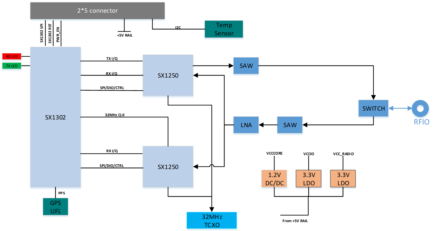
Semtech Block Diagram of "Corecell" gateway reference design (Semtech Corecell Reference Design Users Guide)
Since I was trying to avoid spending hundreds of dollars if I could, I did briefly consider building my own gateway PCB based on this architecture. However due to the ongoing “Chipageddon”, I couldn’t actually get my hands on bare SX1308 chips. In the end I found that the Pycom makes an expansion board for their Wipy microcontroller modules that turns them into a LoRaWAN gateway. Now, I wasn’t interested in actually using a Wipy or their associated software, but the “Pygate” expansion module is essentially a copy of the Semtech reference design above that I could pick one up for $52 from Mouser.
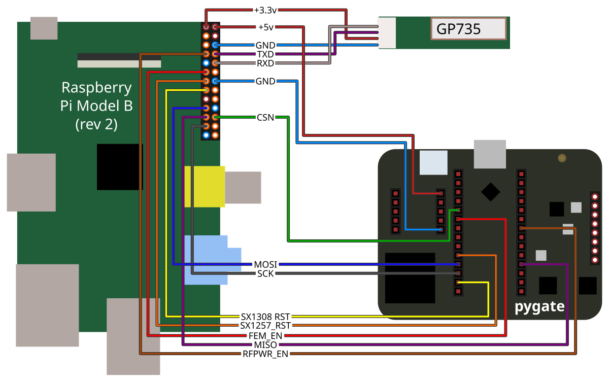
To make a full gateway device, I connected the Pygate module to an old Raspberry Pi (Model B rev. 2) and a GP-736 GPS module that I had laying around. The GPS module unfortunately does not have a 1pps output that can be used for very precise timing. But even it’s limitations this it is sufficient to build an equivalent system to the Corecell reference design, and more importantly, works with the Basic Station software from Semtech.

Gateway Software
To go along with Semtech’s Corecell reference design, they also provide the source for an packet forwarder application they call LoRa Basics Station. This software contains the code to drive the SX1308 and SX1257 chips on the Pygate board, and read timing and location information from a standard NEMA GPS data stream and. This application connects a LoRa network server to forward packets between end devices and the LoRaWAN network.
Building the Basics Station software turned out to be fairly straight forward. In fact Semtech have already put in the hard work to get it building on Raspberry Pi, so it’s as simple as:
|
|
We will get into configuring and running the software a bit later, as that turned out to be the tricky bit, and requires some understanding of the rest of the network servers.
While the Basic Station software was already set up to drive the whole SX1308/SX1257 chipset at runtime, it didn’t handle everything for me. Specifically, the Pygate board has four input pins that must be driven correctly by the Raspberry Pi before it will work:
- RFPWR_EN: Enable signal to voltage regulator for RF power rail. Needs to be driven high to power RF front-end.
- FEM_EN: Enable signal to RF front-end. Must be driven high before enable front end circuits.
- SX1308_RST: Active high reset for SX1308 chip. Can be driven high to reset SX1308 chip, must be low at runtime.
- SX1257_RST: Active high reset for both SX1257 chip. Can be driven high to reset the SX1257 chips, must be low during operation.
While these possibly could have been tied high and low respectively, I connected these signals to Raspberry Pi GPIO pins and used the following shell script to power up the Pygate board and bring the chips out of reset:
|
|
One advantage of driving these enables/resets from GPIOs is that I can also reset or power down the whole LoRa chipset remotely using another shell script:
|
|
Servers
With the network hardware figured out, I just just needed the core LoRaWAN servers and an application back-end to send data to. For the LoRaWAN core servers ended up choosing to use ChirpStack. It provides an integrated solution for the full LoRaWAN network core that is simple to self-host, has many back-end integrations out of the box, and is open source. For my back-end application I’m starting with logging messages to an InfluxDB time series database.
All the details of the ChirpStack architecture, can be found in their architecture documentation. Depending on the size of the network, and applications being run over it, ChirpStack can be deployed in different ways, but for my initial setup, this is what I architecture ended up landing on:
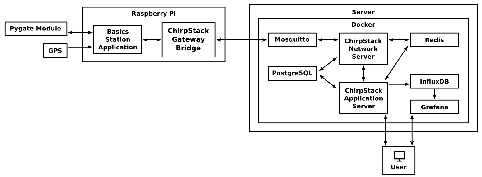
ChirpStack On the Gateway
To connect the Semtech Basic Station packet forwarder into the ChirpStack infrastructure we need to use the ChirpStack Gateway Bridge. This acts as a shim between the Semtech LNS protocol used by the Basic Station packet forwarder and the MQTT protocol and API used by ChirpStack2. We have the choice of running the Gateway Bridge either on the Raspberry Pi gateway or on the server with the ChirpStack Network Server, I chose to run it on the Raspberry Pi so that all the external network communication would be happening within the domain of ChirpStack protocols.
Unlike the other ChirpStack components I ended up needing to build the gateway bridge from source, this was because my Raspberry Pi board was old enough that the CPU was not supported by the pre-built ARM binaries. Fortunately this is not too difficult, I just needed to install the Go compiler and run make:
|
|
ChirpStack in Docker Compose
The rest of the chirpstack components and my back-end database I am running on a standard x86 computer running linux as docker containers, managed with docker-compose. ChirpStack conveniently publishes an example docker-compose configuration on this GitHub page: brocaar/chirpstack-docker. This gave me a good starting place but the configuration did not match the server setup I was looking for, and did not include my back-end InfluxDB database. My final docker-compose and other configurations can be found in the prbs23/chirpstack-docker GitLab repository.
|
|
There are a couple main things that I customized from ChirpStack’s default docker-compose file:
- Removed the ChirpStack Gateway Bridge container, because I am running the gateway bridge on my gateway device itself.
- Changed the external facing ports. I have other applications running on this server that already used the default ports.
- Added InfluxDB time series database and Grafana containers to the configuration. Because my first application for this network will be data logging, I’m using the InfluxDB integration with ChirpStack as an easy time series data store, and Grafana to plot the collected data.
Configuring the Network
Now that I have all the hardware and software pieces I need for a private LoRaWAN network, I just needed to configure them to work together. This turned out to be more complicated than I expected, and also poorly documented, so I’ll walk through the important configurations for each component in the system.
Note: The following configuration is set up as a test network. There are multiple authentication and security features available in ChirpStack which I have not configured for this application, but you should be using for a real network.
Network Server
|
|
The network server configuration is located in a file named by default chirpstack-network-server.toml, and primarily configures the connectivity and credentials between the network server and the other components in the ChirpStack architecture. There are however a couple interesting LoRaWAN setting to call out.
net_id: Specifies the LoRaWAN network ID for the network server. The network ID is used to uniquely identify LoRaWAN networks when routing between network servers when supporting network roaming. If you wanted to support connecting end devices through other device’s gateways, then it is necessary to acquire a unique network ID from the LoRa Alliance. However, network IDs0x000000and0x000001are reserved for experimental networks (I consider this experimental), and networks that are not using roaming (which I am not), so this can just be set to0x000000.band: Defines which region from the LoRaWAN Regional Parameters specification is being used for this network. Since my network is located in the US, I have to use “US915” as my band.enabled_uplink_channels: Declares the subset of channels (as defined by the regional parameters specification for the US915 band) are to be used on the network. For reasons we will get into later, only a subset of 9 channels will be enabled.
Application Server
|
|
Since the application server is not directly interfacing with the LoRaWAN network, the configuration here is pretty simple. Really it just needs to configure the connections between it and the databases and MQTT server docker containers.
Gateway Bridge
|
|
In addition to setting up hosts and ports for the connections to the network server and packet forwarding application, this configuration is where we define the receive channels that will be used by the gateway. To understand how these settings should be configured we need to understand two things:
First, we need to know how the regional parameters specification defines the LoRaWAN channels for our region. In my case the US915 LoRaWAN Regional Parameters specification defines 72 uplink channels. The first 64 channels are defined as 125khz wide channels spaced every 200khz starting 902.3Mhz. The remaining 8 channels are 500khz wide spaced every 1.6Mhz starting at 902.3Mhz
The second thing to understand what is supported by the SX1308 radio baseband chip. The SX1308 has 10 independent receive demodulation data paths that operate in parallel. Channels 0-7 are fixed 125khz LoRa demodulators with independently controlled frequencies, which can demodulate all LoRa spreading factors simultaneously. Channel 8 has a configurable LoRa demodulator that supports 125khz, 250khz, and 500khz channel bandwidth and a configurable frequency and spreading factor, but can only demodulate a single data rate at a time. Finally channel 9 is a (G)FSK demodulator that is used to support the LR-FHSS channels, which use frequency hopping spread spectrum modulation instead of the LoRa chirp spread spectrum modulation used by the other channels.
Given this, these are the important settings from the gateway configuration:
region,frequency_min,frequency_max: These simply define what LoRa region that the gateway is operating in, which for me is the US915 band, which operates between 902Mhz and 928Mhz.backend.basic_station.concentrators.multi_sf: This specifies the channel frequencies for the first eight channels of the SX1308. Note that since the regional specification defies more 125Mhz channels than the SX1308 has, we have to pick a subset of the defined channels. I am simply using the first 8 128Khz LoRaWAN channels.backend.basic_station.concentrators.lora_std: Thefrequency,bandwidth, andspreading_factorvalues in this group configure demodulation channel 8 in the SX1308. Since we already have 8 125Khz channels configured, I am using this channel for one of the 500khz channels, specifically LoRaWAN channel 64.
Gateway Packet Forwarder
|
|
Finally the configuration for the Basic Station packet forwarder application just needs to be configured based on the hardware setup of our gateway. The important settings here are:
lorawan_public: Setting this option tofalsewhich changes the LoRa sync header byte from the specification’s0x34to0x12. Since the sync header is used to identify the start of a packet, changing the sync header prevents packets on our private network from interfering with any public LoRaWAN network.clksrc: This indicates which of the two SX1257 radio front-ends generates the 32Mhz radio clock for the SX1308. On the Pygate module this is the second SX1257.radio0/radio1: These groups configure the two SX1257 front-ends connected to the SX1308. The main difference between them is that on the Pygate module, the “radio0” transmit path is hooked up, and it is not for “radio1”.pps: Since my GPS module does not have a PPS output that I can connect to that SX1308 chip this gets set to false.
Setting Up an Organization and Application
Even once all these configurations are set up, I found I wasn’t done. We need to configure the ChirpStack application server to set up the logical network and applications. This is done through the application server’s web interface.
Once logged into the ChirpStack application sever, we first need to setup the connection to the network server. In “Network-servers”, we add a new network server with a logical name for the network, and the host:port for network server. The host and port should be “chirpstack-network-server:8000”. This is also where we could set up TLS authentication and encryption between network and application servers.

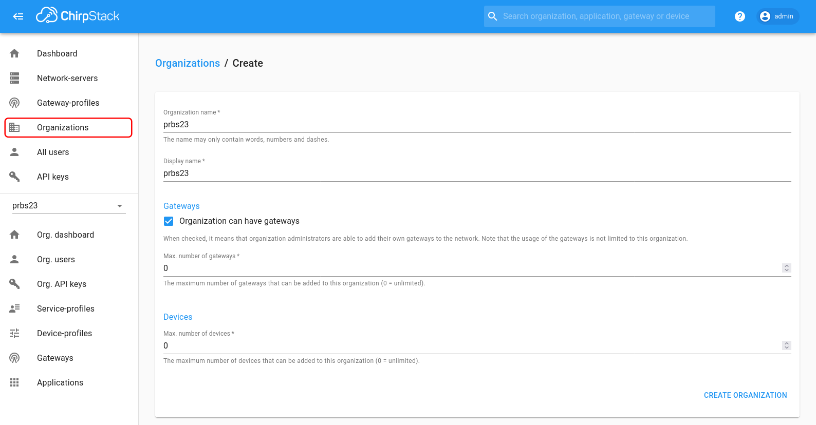
Next we must create an “organization” for our application network to run in. ChirpStack appears to be built from a network administrator perspective, and so provides “organizations” as a way to manage groups of users and applications. For a private LoRaWAN network this isn’t particularly useful, but we still need to set one up. Under “Organizations” we create a new organization a name, display name and permissions. For the permissions I selected “Organization can have gateways”.
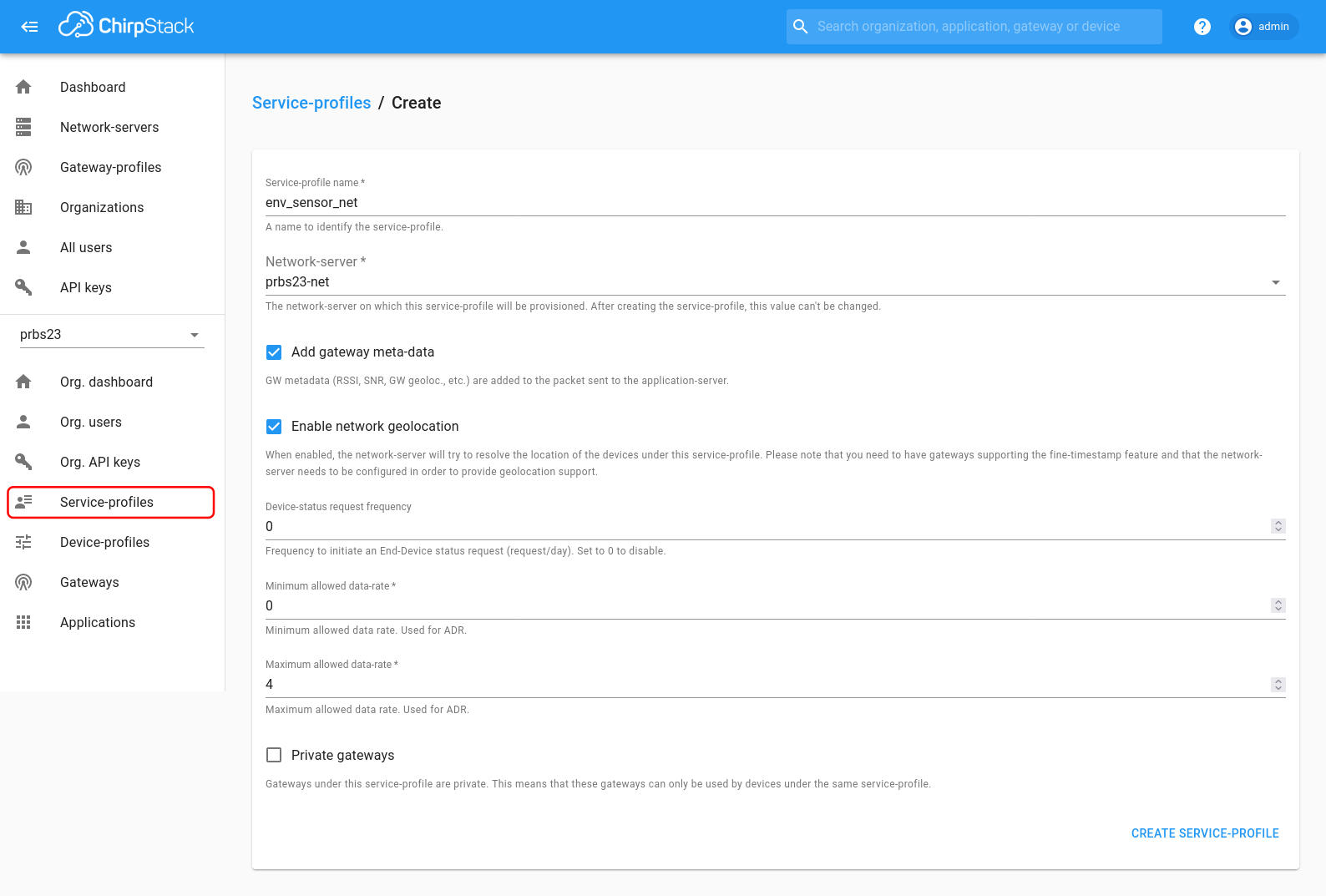
Now that we have an organization, we need to configure the service and device profiles. Each gateway and application is associated with a service profile that defines how the application/gateway can consume network resources. Each device is associated with a device profile which defines network and protocol parameters that are applied to a set of devices.
First we create a new network service profile under “Service-profiles”. The profile has a name, an associated network server (we only have one option here), and other network settings. The ChirpStack defaults have the maximum allowed data rate set to DR0, which is the slowest LoRaWAN data rate. For our gateway configuration, the highest supported data rate is DR4, so setting the maximum allowed data-rate setting to 4 allows us to get the most per-device bandwidth out of the network.
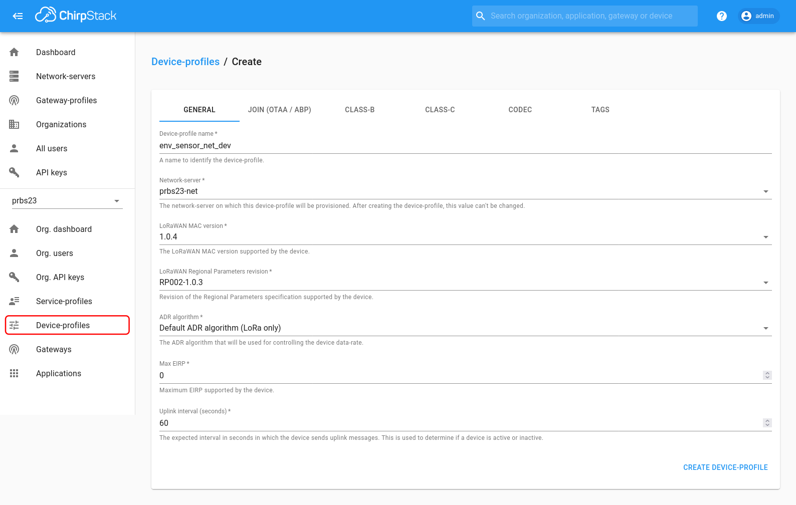
Next we create a device profile by under the “Device-profiles” sections. As with the service profile we need to give it a name and an associated network. Additionally we need to set the LoRaWAN protocol and regional parameters specification versions that will be used by the device. I’m using protocol spec version 1.0.4 because it is what was supported in the end-device firmware network stack, and regional parameters version RP002-1.0.3, since that is the latest version. Finally we need to configure the automatic data rate algorithm to “LoRa Only”, Since our gateway isn’t configured for LR-FHSS. On the “Join (OTAA/APB)” tab I also set “Device supports OTAA” to enable over the air activation protocol which allows the end-device and network server to negotiate network parameters without needing them to be configured out of band.
To simplify logging data into my InfluxDB backend, I chose to enable the “Cayenne LPP” codec under the “Codec” tab of the device-profile settings. When enabled, the ChirpStack application server will assume uplink packets from devices with this profile are encoded with the Cayenne LPP format, and automatically decoded them. This makes it simple encode basic binary values on the end-device and have them logged into the InfluxDB database in a meaningful way.
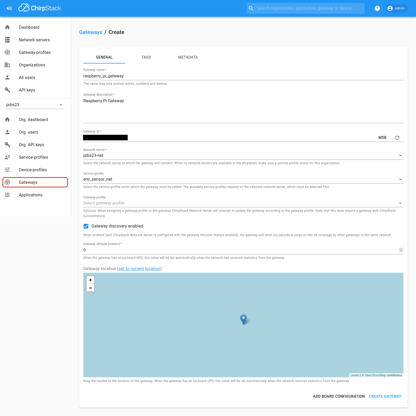
With the profiles created we can now add a gateway to the organization. To do this, under “Gateways” we create a new gateway with a name and description, gateway ID, network server, and finally a service profile. The gateway ID is defined by the Basic Station packet forwarder application and by default is set to the MAC address of the primary network interface on the gateway. The network server and service profiles should be configured to the ones we have just created.
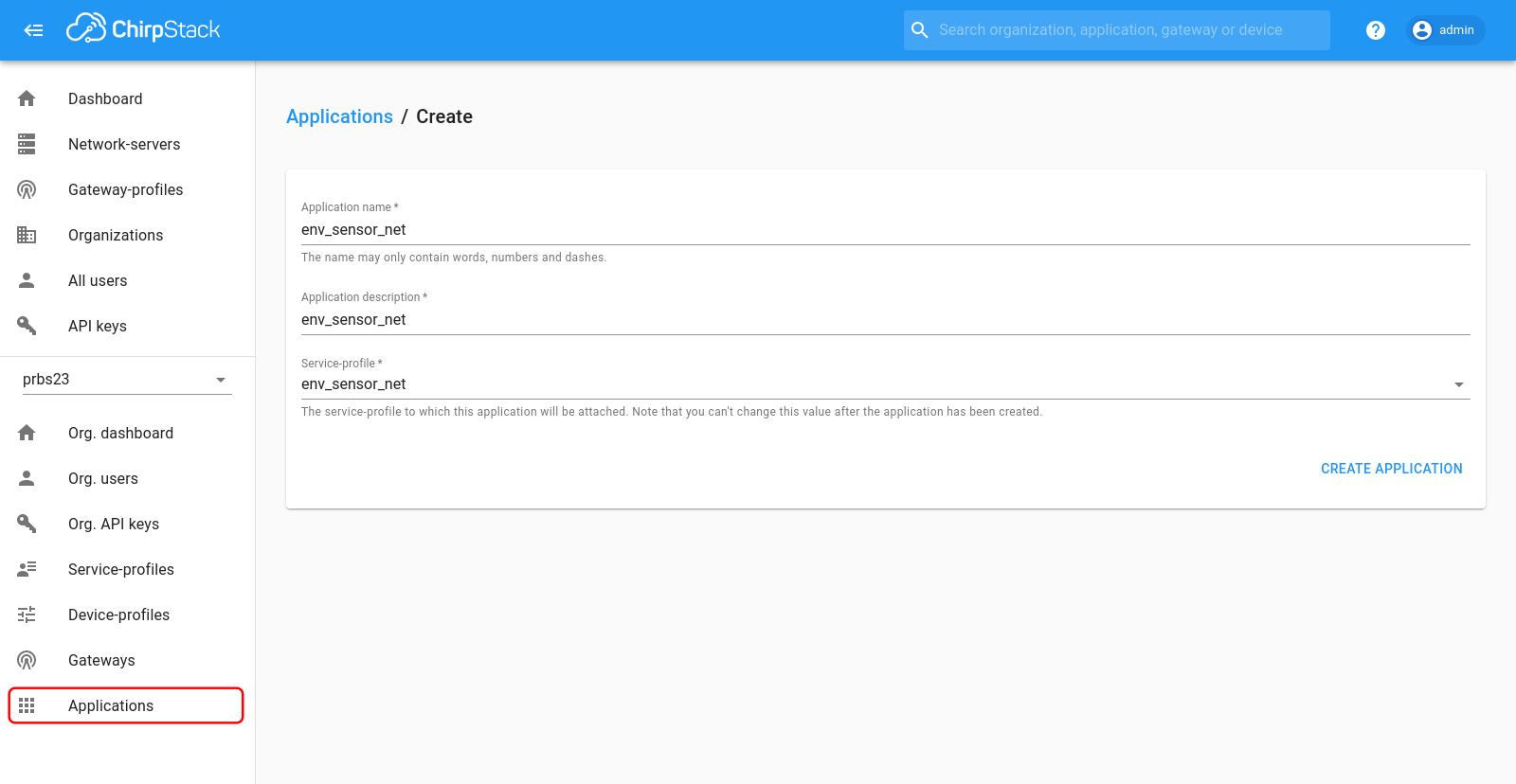
Next we will finally set up the application that runs on top of our LoRaWAN network. To do this we just create a new application with a name and the service profile that we created previously.
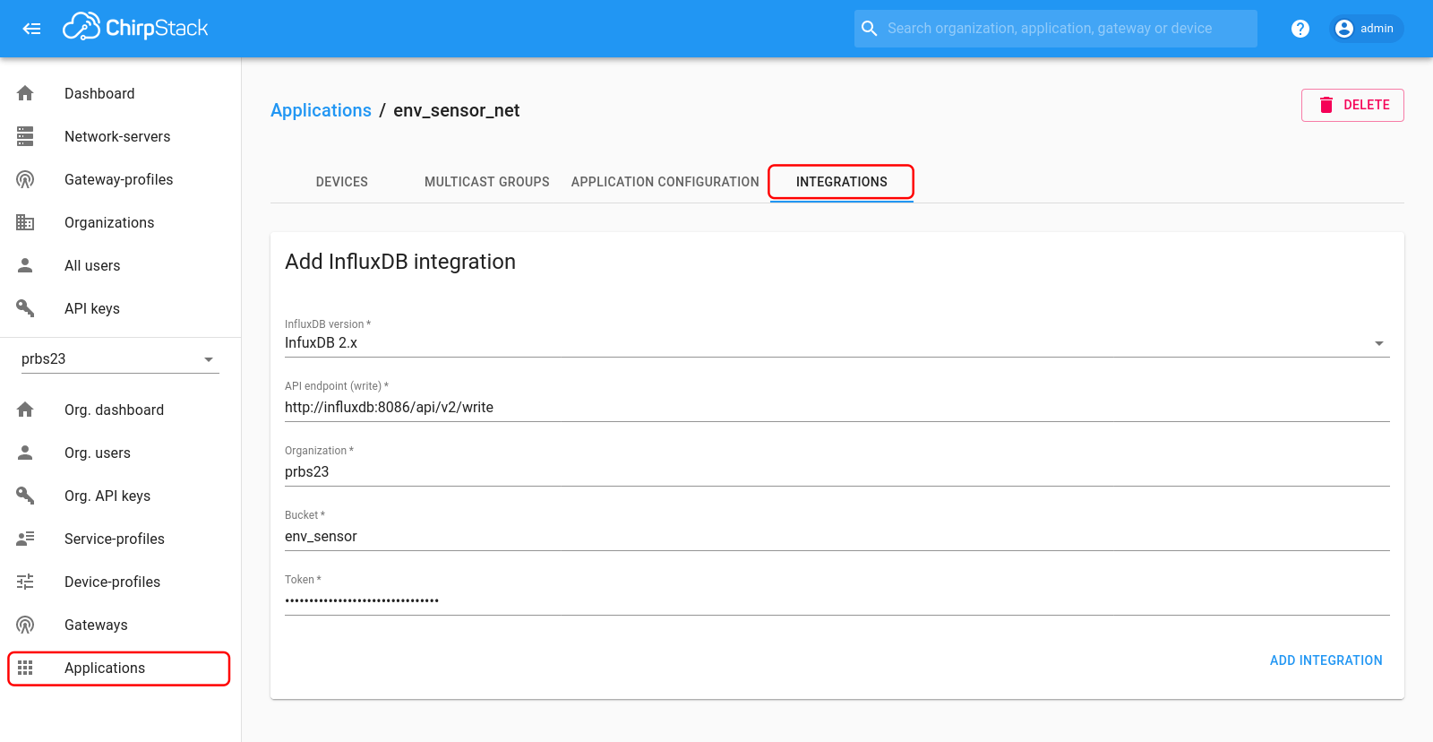
Once we have an application we need to tell ChirpStack what to do with packets once they are received, by choosing one or more “Integrations”. My goal for this initial setup was simply to log data into an InfluxDB time series database, conveniently ChirpStack has an integration with InfluxDB which stores data values from each uplink packet as decoded using the Cayenne LPP protocol. To enable this, under “Applications”->“Integrations” we find the “InfluxDB” integration, add it to the application, then in the integration settings we will select InfluxDB 2.x for the protocol, http://influxdb:8086/api/v2/write for the API InfluxDB endpoint (this is the docker internal hostname and port), and specify which bucket in the database it should put received packets into.
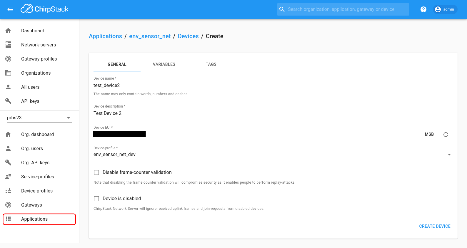
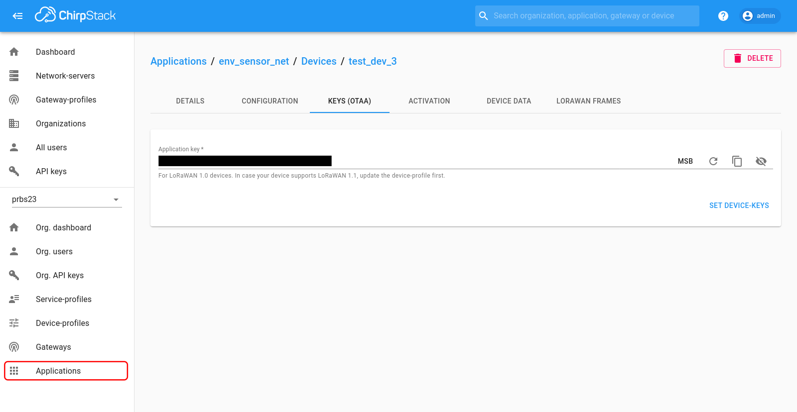
Now we can finally add a our end-device to the application under the “Devices” tab, by selecting create and entering a device name, description, device EUI, and the previously created device profile. The Device EUI is a globally unique IEEE EUI64 identifier for the end-device, the CMWX1ZZABZ transceiver module comes pre-programmed with a Device EUI which will be used by firmware when sending join requests.
Once the device has been created ChirpStack brings us to a page to enter or create an “Application Key”. This is a shared 128-bit key used by the end-device and network to derive encryption keys for all data sent across the network. It should be set to something random, and communicated to the end-device out of band.
And that’s it! Our network and applications are set up and ready to go!
Sending a Packet
As previously mentioned, to test out the network I am running an example application which turns the CMWX1ZZABZ module into an AT style modem. I’m connecting to the modem firmware over the USB-Serial interface provided by the ST-Discovery development board I’m using.
When the module comes out of reset we get the following output:
1
2
3
4
5
6
7
8
9
10
11
12
13
14
APP_VERSION:        V1.1.0
MW_LORAWAN_VERSION: V2.3.0
MW_RADIO_VERSION:   V1.1.0
###### OTAA ######
###### AppKey:      2B:7E:15:16:28:AE:D2:A6:AB:F7:15:88:09:CF:4F:3C
###### NwkKey:      2B:7E:15:16:28:AE:D2:A6:AB:F7:15:88:09:CF:4F:3C
###### ABP  ######
###### AppSKey:     2B:7E:15:16:28:AE:D2:A6:AB:F7:15:88:09:CF:4F:3C
###### NwkSKey:     2B:7E:15:16:28:AE:D2:A6:AB:F7:15:88:09:CF:4F:3C
###### DevEui:  XX:XX:XX:XX:XX:XX:XX:XX
###### AppEui:  01:01:01:01:01:01:01:01
###### DevAddr: XX:XX:XX:XX
ATtention command interface
AT? to list all available functions
From here we can send the commands to have our end-device join the network. First we need to set the NwkKey to the “Application Key” we configured in the ChirpStack UI previously, then send the join command:
|
|
When everything works correctly I get an output like the following, indicating that we have joined the network.
|
|
To send a packet we use the AT+SEND command which takes three arguments: The LoRaWAN port, which can be anything other than 0 (port zero indicates network management packet), a 1 or 0 indicating if we want the network to confirm receipt of the packet, and finally the data to send as a hex string. Since I have configured ChirpStack to decode packets using the Cayenne LPP protocol, the message I’m sending is formatted using Cayenne LPP. The following command will send a packet with a value of 4.00 for the “Analog Input 3” value on port 100.
|
|
In response the firmware gives us this output indicating that it sent our message and it was confirmed by the network:
|
|
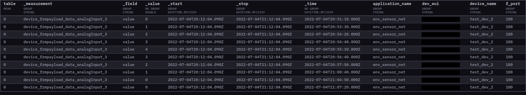
After sending a few of these messages, looking in the InfluxDB bucket I now have the data values from each packet I sent logged into the database, along with a little bit of metadata about it.
Success!
Next Steps
Now that I have a working LoRaWAN network, there are several areas that I will be investigating in the future.
To start with I have just been using the built in InfluxDB integration and Cayenne LPP packet format built into ChirpStack to log basic data. Of course the LoRaWAN network supports sending any data with any protocol, so now that I can reliably send data there are a lot of options of both custom and built in protocols that can be layered on top of LoRaWAN and ChirpStack.
Additionally, I have just been using the CMWX1ZZABZ as a dumb modem to manually transmit packets/data over the network. For a real application of my LoRaWAN network I need to develop firmware for the CMWX1ZZABZ to actual interface with sensors and send the data to the network.
Finally, as previously mentioned I have not configured all the authentication and authorization features in the ChirpStack architecture. I need to spend some more time investigating and learning how to configure these to better secure my network.
-
Technically in some regions such as US915 it is valid to only support a single channel, in which case a single transceiver could act as a gateway. A proof of concept implementation for this can be found in this “Single Channel LoRaWAN Gateway” project on Github. However in other regions such as EU868 region, for example, a gateway is required to support at a minimum of three specific channels. ↩︎
-
Theoretically ChirpStack also includes its own equivalent to the Basics Station application, in the form of Concentratord. However on the integration between the Concentratord and the Gateway Bridge is currently listed as “experimental”, so I have not actually tried this out. ↩︎