I recently wrote about detecting driver strength in SystemVerilog. That work actually came out of solving a larger problem: How do you build a bidirectional digital wire model that includes propagation delay?
Motivation
The problem I had was how to model, in a digital simulation, the behavior of a “channel” (wire) for a high speed SerDes link. At the symbol rates used for modern high speed SerDes links, we start running into the physical limitations of copper as a conductor: the attenuation, frequency response, and speed of signals propagating through the channel are all factors that cannot be ignored as they might usually be. An additional requirement that my channel model had, was that it needed to be bidirectional. For my gate models to function, I not only needed to model the propagation delay of signals through the channel, but I needed drive strength resolution to resolve the value of the channel with drivers on both ends.
The protocol for the PHY I was modeling specifies that the transmitter should only be enabled when it detects that there is a receiver connected to it. The way this detection is done is by having the transmitter sense the presence of the termination resistor in the receiver. This is convenient because it lets the transmitter do endpoint detection without any extra wires, but it does complicate the channel modeling, because a lot of SystemVerilog constructs do not resolve drive strengths in both directions.

A First Attempt
While constructing a model that could inject bit flip errors and remain bidirectional was a little tricky, its not too difficult with the right set up of tranif gates. What turned out to be the tricky part was modeling propagation delay, because as far as I could find, all SystemVerilog constructs which introduced a delay, also behave as unidirectional drivers. So, how can I make a module where a driver change on either port will appear, after a delay, on the other?
Breaking Down The Problem
An important thing to remember is that in SystemVerilog a net value is really a combination of two components, a value (0, 1, z, or x), and a strength (highz, weak, pull, strong, or supply). It’s easy to to delay the value part, but in SystemVerilog this always loses the strength part. Considering this, I hypothesized that if I could decompose the net value into two separate signals (value and strength), then recompose them on the other side of the delay, I could make a strength preserving delay module. If that works, then I could put two of those circuits back to back to make a truly bidirectional delay module.
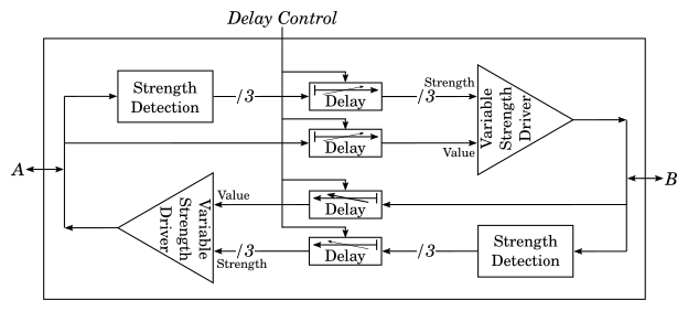
The basic idea was to first build a strength maintaining delay element. To do this I needed three pieces: To decompose the net value I needed a strength detector which would take in a net, a output a value proportional to the strength of the net’s driver. To recompose the net value I needed a variable strength driver which would take in two “values” a net value and a net strength, and would drive an output net with the specified strength and value. Finally I would need a controllable delay element so that the delay could be controlled by my testbench. Once I had the unidirectional delay, I could put two of these back to back, as shown in the system schematic below, to create the bidirectional delay I needed.
First, I needed a way to convert the strength of a driver on a net to a SystemVerilog value. This turned out to be a deep hole all on it’s own, and I’ve already written about it at length in my last blog post. There are a couple ways of doing this doing this with different trade-offs, but for the purposes of this model I used the Verilog only “sense net” strength detection method because it’s a nice fast standalone implementation. It detects supply strength drivers as strong but that was okay for my use case. The code for that is shown below, for details on how it works, that can be found in my previous post.
|
|
The next piece I needed was a module that has “value” and “strength” inputs, and will drive an output node high or low with the given strength level. There turns out to be a few ways to do this, but the cleanest approach I found was to use two assign statements for each strength level: One which can only drive a '1 value with the given strength, and one which can only drive a '0 value with the given strength. Then the value of the assign statement is the “value” input ORed or ANDed with a strength value comparison so that only the correct assign statement is active for the given value of the “strength” input. The code for this module looks like the following:
|
|
Finally, the programmable delays could be simple assign statements with a delay value. Since I’m breaking up the strength and value of the signal, and providing independent data paths in each direction, there is no need to try to preserve drive strength in these assignments or use bidirectional gates.
Putting It All Together (For The First Time)
Now that I had all the pieces, I just needed to stick them together and try it out. For each of the two inout, I created a “sense_strength” signal that was the value representation of that net’s drive strength, and two reg signals to hold the delayed value and strength values for the multi_strength_driver, from the other side of the link.
|
|
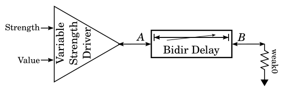
To test my solution I created a basic little testbench. On one side (side A) of my delay module I put another instance of my multi-strength driver module, so I could dynamically control the strength of the driver on that side, and to the other (side B), I placed weak strength driver to 0
For initial turn on I used a sequence that would start by driving a strong1, decreasing strength down to highz, and then increase the strength back to strong with a value of 0 on the net a. Between each step I used a 10ns delay, and the delay element was set with a fixed 2ns delay.
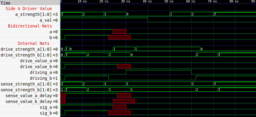
Unfortunately, my initial results were not what I was intending, I expected that the b net would be initially high, transition to 1'bx 2ns after the a driver changes strength to weak1, and then transition low 2ns after the a driver transitioned to highz. The a net should have been high until 4ns after the a driver strength goes to 1, when it should to go to a 1'bx. After the a driver goes to a strength of zero it should be pulled low by the pulldown on net b. What the simulation results, as seen below, actually showed was both nets a and b being driven high (with a strong driver) until the driver on side a drove a strong0, when both sides go to strongX.
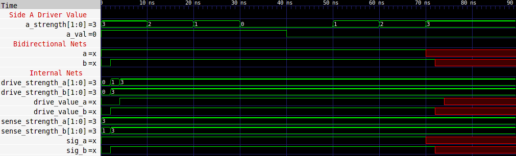
Simulation waveforms from initial bidirectional delay module showing positive feedback latch behavior.
While not the intended result, an astute observer may have predicted this behavior simply from looking at the initial simplified schematic. By putting two of the same strength preserving delays back to back, I created a positive feedback loop in the net strength. After 2x the delay duration from time 0, the variable strength driver inside the delay module wll be driving the same value and strength as the strongest external driver on either side of the delay. If the external driver changes value or strength the internal driver will continue to drive the old value for 2x the delay duration. Unless the net is externally driven with a larger strength than it was before, the net will continue to hold the old value. This is somewhat akin to the latching behavior you get from a unity gain amplifier with positive feedback.
Breaking the Feedback Loop (a more correct delay)
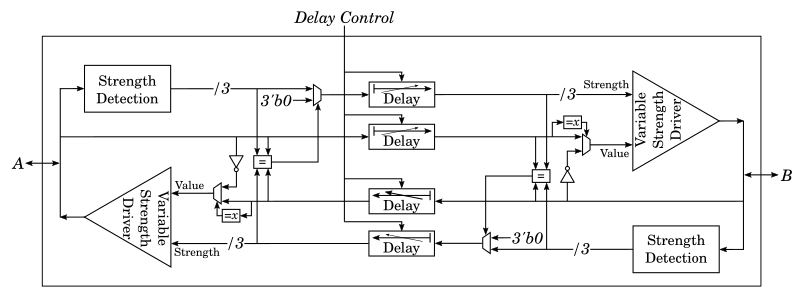
To actually make this delay element to behave correctly, I needed to break the positive feedback loop caused when one of the variable-strength drivers in the delay element is the strongest driver on it’s net. I found that this is possible by only enabling the driver on port b when the driver on port a is not driving the net, and vice versa. While there isn’t a (native) way to know which driver is driving a net, a close enough approximation is if the detected value and strength of the net matches the value and strength inputs to the variable-strength driver on that net. If the strength and value match, then the driver on the opposite port is disabled, which breaks the feedback loop.
While this is actually a conceptually simple way to break up the feedback loop, the trick turned out to be expressing it in SystemVerilog such that it wouldn’t cause zero-time loops in the simulator when resolving the bidirectional net values. After a decent amount of experimentation, the solution turned out to be correct partitioning of always blocks and some well placed #0 delays to force net resolution order. Note that there has to be some additional special handling for 1'bx values, because they can be the result of multiple drivers on one net. The code for my final bidirectional delay module is shown below.
|
|
Using the same testbench as before, simulating this modified delay module resulted in the waves shown below. With the positive feedback loop broken, we now get the expected behavior on the bidriectional nets. The a node gets pulled down by the pulldown on net bafter the 2x delay period, instead of latching the strong value, as the old implementation did.
Simulation results of bidirectional delay module showing expected behavior, after breaking feedback loop.
Remaining Issues
The most significant remaining issue with this design is that if the delay port is set to 0, it can cause an infinite zero-time loop in the simulator. For my use case, the I was able to externally ensure that the delay input never was set to 0, but if this was not possible, one could also add tranif gates to disconnect and bypass the drivers when the delay input was set to zero. The other significant issue is that it cannot handle supply strength net values, mainly because of the approach used to sense the net drive strength. If this was a significant issue, the DPI drive strength detection implementation from my previous blog post could be used in place of the sense-net one I used.
Conclusion
While there are still some corner cases with this bidirectional delay implementation that don’t quite match with reality, it has proven to be fairly solid in production. The fact that it was possible to implement in pure SystemVerilog is both convenient, and means that it should be portable to any simulator. In the end, this project gave me the opportunity to really dig into the details of how net resolution, strength modeling, as well as gate primetives actually work in SystemVerilog.
If you would like to play around with my bidirectional delay module, you can find an implementation on EDA Playgound here: https://www.edaplayground.com/x/2PdE